Friday 30 October 2009

Presentation day

The group is made up of Richard, Stuart, Tom and myself. Richard and I began early to create aspects of the model. I focussed mainly on the base of the machine and the structure that will eventually hold all of the components that we will animate.
Richard began creation of the fly wheel and Tom began to create some more detailed aspects, such as bolts that will be replicated across the model.

As can be seen from my previous posts, I have already sucessfully created the base of the model, which I shall be building up over the next few days. Then I shall progress on to creating some of the main arms that are animated in the middle of the model. As there are four main sections to our model that we chose, the tasks are easily spread across each member of the team.

The presentation:

Prior to the presentation, I created a few powerpoint slides containing information about our project. Things like roles and responsibilities, foreseeable problematic areas etc. I feel that this presentation went very well and it gave every member within the group a chance to explain to the rest of the class what our project is all about and how we will go about completing this project.

Our presentation was widely accepted by Jo Bowman and the class, and as a team we have a direct goal and specific aims that we know we must complete. The team are now ready to get to work on creating the model, and the work that has been created so far is looking very promising.

The slides from the presentation are shown below:


These sites showed us how the machine was created and also provided us with more pictures that we will be able to use for animation purposes. Background information on the machine also provided us with knowledge of where it would have been used, so hopefully we will be able to create a model in 3DS Max of a colliery to add to the affect of the machine working.

Thursday 29 October 2009

Experimenting with texture

I felt at this stage that it would be appropriate to experiment with some textures. The primary reason for this is that I wanted to see what the model would look like once I have applied the textures to this section.

First, I imported my original image into photoshop and cut out a section of the front wooden beam. I then saved this image in photoshop.

Then, using the material editor within my 3D Studio Max file, I selected the diffuse channel, and chose bitmap as my selection. I then selected my image so that it appeared within the material editor pane. Dragging and dropping this image onto the object showed the material on it. However, I decided that the effect was not wooden enough, so I decided to change some of the properties.

First, I changed the bump map within the material editor, so that the image appeared with more texture to it. I did this by dragging and dropping the Map file down to the bump section within the Maps parameter. This, as expected, made the texture look more as if it was actually a wooden object.

(Using the bump map editor)

One final touch that I did to make this look even more realistic was to add a 'Strauss' effect within the 'shader basic parameters'. I increased the glossiness up to 87 originally, but then moved this down to 50 to give a duller effect on the wood. I was then happy with the results and the effects shown on the object, and could repeat this process for the other pieces of wood.


(Using the Strauss option)

So that all of the pieces of wood did not have identical patterns, I altered the wood texture image slightly in photoshop and saved it as a different file name. The main alteration, among others, was to remove the wood chip on the front face. I then used this new image to map to the various objects in 3D Studio Max, using exactly the same technique as before when doing the front wooden block. The image below shows the final result.

(Wooden blocks rendered)

The completion of the wood material then spurred me on to add a material on to the metallic base of the frame. I completed this much in the same way as I did for the wood, except by using an anistropic shader instead. The source image was a grey paint texture that I found from the Internet. I then imported this into photoshop, and placed a fill colour behind. I then made this partially transparent so that the texture came through. By using the 'bump map' option in 3D Studio Max, the texture came through nicely as expected.


(The final rendered image of the materials)

Creating the base

(Initial stage of creating the base model)

To create the base, I started of by drawing 2 chamfer boxes. I did this by selecting 'Geometry' then choosing 'Extended Primitives'. Within the object type, I then chose 'ChamferBox' and drew a rough box. The chamfer box option is shown below:

Then, using the parameters section, I could then scale the boxes to the correct size. The first box that I created measured 60.96cm in length and 10.95cm in width. The height was 14.99cm. I could also set the fillet level to 0.51cm so that the edges became rounded rather than completely square. Placing this object in the correct position as per my reference photograph, I then used the clone tool to create an exact copy and placed the second object where it needed to go. The clone tool setting that I used for this is shown below:
Now that both side boxes were complete, I then created the middle chamfer box, as shown in the image above. Doing this in the same way, I selected the same depth for this object, and made sure that it was wide enough to fit between the first two boxes without a gap between. I then made sure that the fillet level was the same as per the other two boxes that I created.


(Boolean tool used to join the base of the machine)

Having finished the main base structure, I then decided to continue to build the model by starting on the base of the machine itself. Firstly, I created a chamfer box, similar to the way I created the main base, and made this large enough to cover the area that was required. This chamferBox only needed to be approximately 4 cm tall. I then created a smaller box for the front of the base. Selecting the larger base box, I then used the boolean tool and clicked 'Pick operand B'. This then allowed me to select the small box at the front to make a 'cut away' from the main box, leaving me at the stage where the image above shows. I then placed the small box into the larger box so that they fit closely together.

The last stage was to create the section of the base of the machine that connects it to the main wooden base. To do this, I used the line tool within the top view to draw the shape that I wanted when looking from above. I then selected the sides and used the extrude tool, making sure that it was the same height as the main base of the machine. I then used the smooth modifier to make it look smoother, and connected it to the main base of the machine. Finally, I created a square on top, which I will alter at a later stage to make it chamferred around the edges.

(Bolt that connects the wooden base to the machine base)

Tuesday 27 October 2009

Setting the units

Before opening 3D Studio Max and creating the model, I decided to obtain a conversion table, so that I could convert Centimeters to feet, and visa versa. The table that I found on the Internet was the one below:

(Conversion table)

Using this conversion table, I will keep to the measurements of the pump, which will be particularly useful in later stages when the group collates ideas.

Now that I have the correct conversion data, the next thing that I did was to change the unit settings in 3D Studio Max. To do this, I went to Customize - Units setup, then made sure metric and centimetres were selected. I then clicked system unit setup, and again selected centimetres. This then changed the measurements within 3D Studio Max so that I was then working with Centimetres, so that any objects I created, were then related to this scale.

(Converting the scale to centimetres in 3D Studio Max)

The scale of the pump is 4x2x4 feet. So that I keep to these specific measurements, I decided to draw a plane just beneath where the model will be placed. I made this 120.92cm x 60.96cm so that it was equivalent to 4 feet wide by 2 feet deep. Later on in the project, I shall create another plane that will give me the guidelines for the vertical measurements. To create this plane, I selected 'geometry' and used 'standard Primitives'. Within 'Object type', I selected plane, and drew a rough square in the top view. I could then alter the width and length measurements within the parameters section.


(Plane created underneath where the model will go)

Thursday 22 October 2009

Museum of Power - Initial thoughts

On Wednesday, 7th October, our group (Tom, Stuart, Richard and myself) went down to the Museum of power in Langford, Maldon. When we arrived, there were many various machines that looked promising to use for our 3D animation project. Some machines I was familiar with, but others I had not seen before. Some of the machines that we came across were really too large to use for our project.

Eventually, after some consideration, we decided to use the Joseph Evan's reliable steam pump. This appealed to us for several reasons. Firstly, there were three main visible moving parts which would be ideal to model and animate in 3D Studio Max. Secondly, the size of the model was ideal; 4 feet x 2 feet x 4 feet is an ideal size to use for both taking photo's and using as a specimen for modelling.
The attractive colours and the typical engine noise helped to make this model appealing to us from the outset.
The machine was built in 1929 and used as a Crude Tar Pump until the end of 1986, where it was then purchased by the museum for ten pounds.
As a group, we ensured that many photo's were taken from various angles whilst the machine was moving and still, and we also took some video footage for animation purposes. The image below is the primary one that the group will be working from in order to create the model. Further down the line, we will all be using other photographs that we took in order to obtain more intricate detail.


(The J. Evan's reliable steam pump)

(Information sheet for the Steam Pump)

Our first team meeting is on Thursday 29th October where we will discuss the various roles within the team and how we will go about modelling and animating this machine in 3D Studio Max. At this point, we will also decide on a scale that we will use for creating the model, so that at the end when we consolidate our models for animation, they will match each other in size and scale. We will be holding regular weekly meetings throughout the project so that we constantly communicate with each other and update each other on our progress and ideas. A powerpoint presentation will follow in week two of this project where we will be able to explain our ideas to other groups, and hopefully get some feedback on what we will pursue.

Monday 19 October 2009

Saturday 17 October 2009

Animation


In order to create the animation above, I used the 'Autokey' function located at the bottom of the screen. I then dragged the 'slide bar' across to a particular time frame, and moved the vertices around accordingly. When I played the movie, the vertices moved smoothly which showed the animation on my model. The main problem I encountered was that as I mirrored the entire model, I could only make animation adjustments to both sides at the same time. Fortunately, I did not mirror the eyes, so I was able to make one of the eyes fall out, whilst the other one looked at it. I made the eye that fell out look like it was compressing at the bottom of the fall when it hit the floor. I did this by using various time frames, and gradually compressing then decompressing the eye. It was then a matter of playing around with the animation until I was happy with the way that it worked and the timing of it.

Final thoughts and reflection

Looking back on the very first lecture for Virtual environments, I remember becoming very anxious about what was being asked of me and what I had to create for this module. Having a very limited experience of 3D Studio Max, and having not used it in over five years, I was concerned about the quality of work that I would be able to produce. As such, I got into the work straight away and started to work through the online tutorials right from the beginning. Looking back, I believe that the key to this module is to follow the tutorials as closely as possible, and always expect things to take longer than they actually do. The online tutorials are very helpful and descriptive, although the voice for the commentary can get a little annoying at times. The only negative aspect of the tutorials is that occasionally they jump forward into the next stage without showing you how they got there. For example, there is no explanation on creating the eyes or the lips. However, these things are relatively easy to work out, and there are several ways of doing them.

Although the most tedious stage was at the beginning, aligning the images and creating polygons, this was also the most important stage. I feel that the model that I created was only successful because I spent so long anally lining up both images and making sure that I did not have any polygons or shapes with more than four sides.

Defining the topology was also very important, because this eventually brought out and highlighted key areas of the face which then made the model look like me.

Converting the 2D mask into a 3D mask was very fiddly and time consuming. I was often unsure exactly where each vertex needed to go, but made sure that they were correct, as I knew that this would later alter the shape of my face and the feature within.

I found creating the nostrils very satisfying. I learned a new technique of using the extrude tool to create the hole in the nostrils. The extrude tool is extremely useful and one that I can take with me and use in other 3D projects that I venture upon. I have also learnt to use other very useful tools, such as cut, weld, connect, break, create, attach and many more.

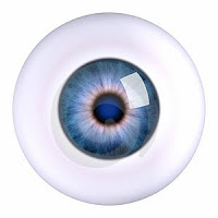
I had great fun creating the lips and eye detail. It was at this point that I really started to feel a sense of achievement with this project and to start seeing a resemblance in my model to my original image.

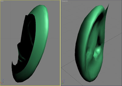
Developing the back of the head and shoulders was very much different to creating the mask. When creating the mask it was all about detail, whereas developing the back of the head and shoulders was more about quantity rather than quality. This does not mean that the head and shoulders are not created to replicate my model, they are simply easier to replicate as the detail is not so specific. Creating the ears proved to be a very difficult task. This was probably the most time consuming part of the modelling aspect, as it was very confusing trying to work out where all of the vertices needed to go and how I could make the ear resemble my original image, particularly with the amount of detail that was required. Once I had welded the face to the rest of the head and shoulders, I could then start to concentrate on the mapping aspect of the project, rather than the modelling.

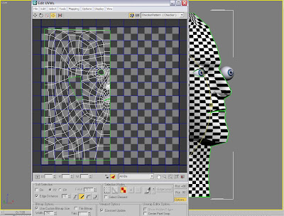
Mapping the image onto the model was definitely the most important, and at the same time difficult, part of this project. I spent approximately 6 days on the mapping alone. I initially thought that it would be a case of using the material editor and copying my image onto the head. This shows how little I originally knew about 3D Studio Max. Nothing is ever that easy! Creating my face template in Photoshop took days to create, and even when I thought it was complete, I still had lots of modifications to make to it when I later view it complete on my model. Once the model was complete and work had ceased, I was overwhelmed by satisfaction that I had created a model that was relatively accurate to my original images. As I finished slightly ahead of schedule, I was also able to create some animation. This was really just to see how my model looked when it moved and if it looked realistic.

Overall, I feel that this project was really beneficial to me. I have learnt a vast amount of knowledge on how to use 3D Studio Max, and feel confident that when I come to creating something else again, I will be able to produce something to a high level. I have learnt to use many new tools in both Photoshop and 3D Studio Max. Spending many hours on this assignment was the only way to get it done, as everything took far longer than I initially expected it to. This module was designed to increase my knowledge of 3D imaging, and for me, it has done exactly that. I have gone from having virtually no knowledge at all, to creating an animated model of myself. I am extremely pleased with the way my model has come out and how it looks very similar to the way I look in real life. If I had more time, then I would animate my model further, which I am sure that I will do further down the line.

During this project, I encountered many problems. I had problems with welding the vertices together, problems with the symmetry modifier, problems with linking the photoshop image up with the model and general modelling issues. I overcame all of these by mainly trial and error. If something didn't work, then I would try it another way. This way, I learnt a lot more as I got an insight into the many different ways in which I could do things.

I have enjoyed this module, and have learnt far more than I thought would be possible within five weeks. I have also learnt many new skills which I will be able to use in the near future.
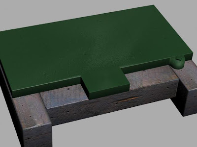
Mapping - Part 2

(Copying my face in photoshop)
Using the original image that I took at the start of the project, I then started to cut parts of my face out of this image and into a new layer on my UVW map in Photoshop. As you can see from above, I did this by copying small patches across from one image to the other. The tool that I used for this was the lasso tool, which was made even easier by occasionally using the magnetic lasso tool to draw around parts of my face that had a line to trace. As the image at the bottom is a higher resolution than then the one above, when I copied the image across, it was far bigger. So, I had to use the scaling tool to make it a suitable size. I could also change the colour and contrast of the image by going to Image - Adjustments - Hue and Saturation. I then merged all of my layers together to become one. Using the rubber stamp tool, I was able to clone a part of my face, then draw over a particular area, which drew an area that matched the cloned area. This tool was very useful for filling in areas where there was no face patch to fill it. Another useful tool that I used was the 'patch' tool. This worked by selecting an area where two or more patches joined, but where a visible line showed. I then clicked this area and dragged it onto another similar area, which then blended in the area that I initially selected. This tool worked very well with the rubber stamp tool, because I could use the rubber stamp to fill in an area, then use the patch tool to join the edges, making it look like one complete image.

(Using the warp tool)

In a specific layer, I went to 'edit - transform - Warp' which brought up the 16 point object, as can be seen above. The warp tool is yet another good tool which I used excessively when mapping my image onto the UVW map. Using the warp tool, it allows me to stretch parts of the object in a particular direction. This was really useful because if a particular shape did not fit very well, then I could use the warp tool to pull it across to cover up gaps or make rounded objects more straight of visa versa.

(Face close to completion)

I continued with this process until the entire face had been mapped across. As can be seen from the image above, I have successfully managed to copy my face image across, and cover up any areas where patches joined. All in all, there are around 20 patches in the image above that I had to merge together to form one complete image. The trickiest areas were the eyebrow and front hairline. These parts proved to be very time consuming and took a lot of time to complete so that they looked natural without any dividing lines.


(Mapped image on my model)

The image above shows how the mapping appears onto my model in 3D Studio max. The way this works is that 3D Studio Max periodically checks any files that are associated with my model and updates them. This is really useful because I do not have to render the image every time. All I simply do is save my photoshop file, and 3D Studio Max automatically updates my model. This is similar to the way that the original photo's automatically updated when I added new topology lines at the beginning of this project. At this stage, I am pleased with the way that the mapping has appeared onto my model, so will continue to complete the mapping process.


(Mapping of face complete)

Continuing the same process of copying patches of my skin onto the image, I finally came to the stage above. It did not take me quite as long to do the right hand side as I was more familiar with the necessary tools required to build up the skin layer. (i.e. warp, patch, rubber stamp etc). I also rotated some of the patches as they were a better fit when I rotated them, rather than just leaving them level.

(The final outcome)

When I saved my photoshop file, then went into my 3D Studio Max model file, I was very surprised at how my model looked. I was initially expecting a model that would contain skin stretching and pinching. However, the skin looked very smooth and with very little pinching. I had to make some alterations to my photoshop file, particularly where the ears met the face. Modifications were made by going into the photoshop file, using the various tools to manipulate the image, then saving it. 3D Studio Max automatically updated the model accordingly. I could notice any errors that needed my attention by using the model, then addressing these errors in Photoshop.

As predicted, the mapping segment of this project was by far the most taxing of all. Arranging the polygons within the UVW edit mode was very difficult and time consuming. It was particularly difficult for the ears as there were so many overlapping lines. Cutting patches out of my face and pasting them onto my main image was also very difficult. This was because I had to make sure that I scaled every patch down to the correct size and arranged them in such a way that there were no dividing lines between them. Although the patch tool is a very useful tool, it is also very difficult to use. Ensuring that two or more joined patches look like one patch is very difficult and extremely time consuming. Even after completing the UVW image in Photoshop, when I looked at it in 3D Studio Max, there were still many modifications that I needed to resolve. Most noticeably, the rendering on the ears did not look correct. So, I had to keep making the alterations in Photoshop so that the shadows on my image matched the indentations on my model.

Monday 12 October 2009

Mapping - Part 1

(Face with Chequered pattern)

Having been pre-warned that this stage of the project is very hard, I was prepared for the mapping process.

The first part of this was to create an unwrap UVW in the modifier list and select 'face'. As the symmetry mode is still present, any work that I did on the right side of the head would automatically get reflected onto the left side. I then coloured the side of my head using the paint marquee mode. I did not colour in the ear at this stage, as I would complete that later on. I then used the cylindrical mode in the map parameters section and arranged the cylinder so that it encompassed all of my model. So that I could see how I was stretching and arranging the material on the outside of my model, I applied a chequer pattern as this made it easier for me to see this. I then went into the 'edit' mode under the Parameters mode.


(UVW's in edit mode)

The above image shows my face model within the edit mode for the UVW's. Within this mode I am able to move the corners of polygons around so that there are no triangles or shapes that I do not desire. This does not alter the model in any way, but instead re-arranges the chequer pattern that covers it. The aim of this exercise it to arrange the mesh so that all of the chequered squares are aligned correctly and that the lines that make the squares are relatively straight. This will give me a good image at the end when I map it onto my model.


(Model after editing the UVW's)

Once I had arranged all of the chequered squares, I then returned to the normal perspective view, which displayed the image above. As shown, most of the squares are now aligned and run in relatively straight lines. This should hopefully give me a good image when I come to mapping it onto it.


(Editing the ear)

Now that the head is ready for an image to be mapped to it, I then moved on to the ear, where I would do a similar process. Selecting the ear, I coloured it in red, then selected 'pelt' under 'map parameters' which stretched out the mapping over my ear, ready to be manipulated. I then selected the 'point to point seam' button and drew a line across the width of the ear, from the head to the outside of the ear (As shown in the image above).

As before, I then went into 'edit' mode again to move the corners of the various polygons around to make straight lines and accurate squares, similar to the way I did when editing the head UVW's.

(Editing UVW's on the ear)

When I entered the edit mode, the 'edit UVW's' dialogue box appeared. This is slightly different to the way I edited the head UVW's as I am in 'pelt' mode, which gave me the ring around the ear (called the stretcher), as can be seen in the image above. To manipulate the mapping on the ear, I used the rotate tool and rotated the stretcher around the ear. When I hit the 'simulate pelt pulling' button, this then stretched the ear according to how I arranged the stretcher around the ear. I continued this until there were no more overlapping parts. I then closed down the UVW editor.

(Head and ears in UVW edit mode)

Within the 'edit' mode of the parameters tab, I am now left with the right side of my face and my right ear when I allow everything to be displayed. I scaled down the ear as it was a lot larger than the rest of my face, and moved it down to the bottom of the viewport. By going to 'view' then 'select inverted faces' or 'select overlapped faces' I could then highlight any areas where vertices overlapped. Next, I made sure that 'select element' was enabled and selected the mirrored image of my face. I then clicked on the 'mirror' icon which created an identical copy of my head, but facing the other way. I did the same for the ear. I then aligned the images of the head up so that both images met down the centre, without a gap in between. This left me with what you can see from the image above.


(UVW Map in Photoshop)

I next created a new layer in photoshop and called it 'guide'. I then chose a bright blue colour and filled in the layer completely. I then copied the background layer (above) in to the 'quick mast' mode, which then gave me a selection of all of the various relevant lines when I exited quick mast mode.

('Guide' layer in photoshop)

Friday 9 October 2009

Adding Eyes

(Defining the eye area)

Before adding the eyes, I decided to create a little definition around the perimeter of where the eyes will go. To do this, I dragged new polygons in towards the middle of the eye from the ones around the edge. I then selected the edges of the polygons that were closest to the centre of where the eye will go, and arranged them so that they were closer to the middle of the head than the next set of lines out. This in turn gave me a ripple effect making the area around the eye protrude further than the area that will connect to the eyeball itself. This produced 3D eyelids on my model.

(Spheres added to make the eyes)

I then created a sphere in the left eye and positioned it where it needed to go, making sure that all of the head vertices were positioned as close to it as possible so that there were no gaps around the eye. Using the mirror tool, I then copied the eye into the other socket to give me both eyes.


(eyes complete)

The last stage was to find an image from the internet that I could use for the eyes. I found this image:


I then played with this in Photoshop so that there was no longer any edge around the eye. In effect, I simply used the blue retina and pupil, and created behind it an off-white background. I then went to 'Image - Adjustments - Hue/Saturation' where I was then able to play around with the hue, saturation and lightness so that the photoshop image resembled my eye both in looks and colour/lightness. This was then ready to be mapped onto my 3D eye model.


Using the material editor, I imported the image of the eye into my 3D Studio Max file in the specular view. I then dragged and dropped this onto my eye which then mirrored it onto my other eye. Clicking the show map in viewport icon, I could then view the eye on the sphere that I had created. I need to offset this image slightly as it did not appear in the centre of the eye as I wanted it to. Once the image of the eye was positioned correctly I then TurboSmoothed the model again to check that everything was as I intended it to be.


Additional detail (19th Oct)

As the eyes appeared too bright, they did not look correct on my model. As such, I went back into the photoshop eye and reduced the white background colour to a more greyish colour. I also added some red lines to make the eye look more realistic and reduced the colour of the iris by editing the Hue/Saturation. I was left with the result below, which looks a lot more realistic.

Wednesday 7 October 2009

Creating the ears

(Part 1 of the topology lines)


Creating the ears are a very similar process to the way in which I created the face. First, I had to draw the initial topology lines around my ear in photoshop, following the contours and direction that my skin goes, and also tracking the main characteristics of the ear.

(Part 2 of the topology lines)

Having created the blue lines in photoshop, I then created the main red lines which will eventually be used to create the polygons in 3D Studio Max. My main aim for the red lines was to create only four sided objects, and not have any triangles. You can also see from the image above that I have ensured smooth curves to flow around the ear.


(Creating the polygons in 3D Studio Max)

As the image plane in 3D Studio Max is mapped to my photoshop image, the image within 3D Studio Max automatically updated when I made any modifications. This enabled me to draw along the lines on the image in 3D Studio Max to create polygons on my ear. I ensured that the snap tool was on for this so that all of the polygons were complete and all of the lines joined up. I did not trace along all of the lines as I knew from experience that it would be best to simplify the polygons, then add extra details later on.


(Converting the polygons to a solid object)

Once all of the polygons were complete, I then selected one of the polygons and converted it to an editable poly. From this, I then selected the entire ear and used the attach tool within the edit geometry mode. Selecting all of the lines I had created to be attached, this then converted every line into an editable poly so that they became ready to be manipulated. Next, I welded all of the vertices together at a setting of 0.4, so that when I move one corner of a polygon, the surrounding ones move too. This makes it very easy for me to shape the model.
(Ears converted into a 3D model)

Similar to the way in which I pulled each vertex out individually to their correct position using the front view when creating the face, I was able to create a 3D model of my ear in similar fashion. I focused on pulling out certain vertices where the ear protrudes most, mainly around the hole in the ear and at the back of the ear. This has proved to be the most difficult stage of the project, as there were some vertices in the middle that needed to be pulled further across to the right than the vertices at the front, meaning that some of the vertices were very close and I really struggled to do this without getting confused where all of the vertices were.

Next, I used the left view to select the 8 polygons that covered the hole of my ear. I then used the chamfer tool, with a setting of 2, which created a duplicate line around them. I was then able to use the front view to drag these polygons into the ear (to the right) which gave the effect that there was a hole going into my ear. I used this technique to also create the depth at the top of my ear.

Eventually, I got to where the image above shows.


(Adding depth to the ear)

Up until now, the ears have had no real depth to them. To add the depth, as can be seen from the images above, I selected the edges around the perimeter of the ear, and holding the shift key, I was able to add a row of polygons to create depth to the ear. I repeated this process, then using the select and non-uniform scale tool, I brought all of the last row of vertices in towards the middle of the ear. These vertices would then get attached to the head further down the line. I also ensured that all of the polygons were filled in, particularly the ones at the front of the ear which are also used to connect the ear to the head.

(Polygons added to ear)

The image above shows more clearly how I created new polygons in order to add depth to the ear. This also enabled me to have several vertices to use in order to connect the ear to the head. As the edges around the ear have been reduced to four sides in the middle, this then makes it a lot easier to attach it to the head.

(The final stage of the ear)

The final stage of the ear creation was to create a mirror image, so that I have one on both the left and right side. I ensured that both ears lined up correctly. I then pulled out the vertices around the ear ready to be attached to the face. Next, I attached the ear to the head using the attach tool, which then enabled me to weld the ear onto the head. As the ears were mirrored to each other, this made things a lot easier, because as I welded the right ear of the head, the left ear also welded at the same time. However, it was very difficult to locate every vertex of the head to the vertices of the ear, especially the ones that were located directly behind the ear itself. I am pleased with how smooth the ear has attached to my head and feel that this model is a good reflection of how my ear actually looks. It was very difficult getting all of the detail included in the ear. Some of my ear detail had to be simplified as it was too complicated to model it to a 100% accurate replication.