Being in the same group as Tom Robinson, Richard King and Stuart Norton, I immediately knew that the work we would eventually produce would be of a very high standard.
The group worked very well together in most aspects and the progress that we made weekly seemed amazing, even as I look back now.
The primary aspect that made the project so successful was communication. Right from the beginning, we agreed on a size scale to use, and this made it very easy later on when the different models were brought together. We met weekly to discuss what we had achieved over the week and set ourselves targets for the following week's meeting. Another key to the group's success was the fact that we managed to complete the main modelling aspect so quickly. This then gave the group more time to work on the animation and lighting/movie segments.
As Stuart lives quite a way from the University campus, it seemed more ideal that we contacted him via e-mail, and met just once a week. The rest of the group met every couple of days.
The workload was shared evenly. I took on the main model, Tom took the left section, Richard took the wheel and individual arm and Stuart took the right section and environment. It was basically a process where once someone had finished working on their section, they then moved on to something else that could be done. For example, after I completed my modelling aspect, I then moved on to creating some environment (ie snow and sky scenery). I also worked with other members to arrange the lighting and to create the final movie. This consisted mainly of arranging the various cameras into the right positions and making sure that the cameras displayed the scenes as we required.
Unlike many groups that have done projects like this before, the team worked really well together. Something that amazed me was the way the group got on with the work and never argued. We all contributed ideas, and then went with whatever the group agreed was the best option.
Throughout this project, I have yet again learnt so many new skills. Having never used 3DS Max before the face project, I have really been thrown into the deep end of modelling. The only way that I overcame my lack of experience was to sit and work through tutorials and spend hour upon hour learning how the software works. I have learnt so much. The techniques that I have acquired have proved really useful. Things like using the Boolean tool, adding and altering textures to display bump maps and anistrophic settings, lighting settings and key frame animations are to name but a few techniques that I have learnt.
The animation was relatively difficult to get right. Key frames seem to have a mind of their own. I had great difficulty when I grouped objects, animated them, then when I went to ungroup them, they distorted and the animation did not work as I required. The animation was also very fiddly, and typical of me (being OCD) I had to make sure that it was 100% correct.
I was initially concerned with creating the lighting effects and also the movie aspect.
However, working with the rest of the team, I soon learnt how everything works, and am now quite experienced in these areas. Creating a movie is a lot simpler than I thought. It is really just a case of placing the camera in the correct place, then moving through the key frames, making sure that it shows in the view port what you want to display.
At the beginning of the project, the group analysed everyone's strengths and weaknesses. This was vital, as it enabled us to work out who would do what within the project, making sure that everyone worked in areas where they were best suited. However, this did not stop us from learning new skills because with all 3d modelling, there is always something new to learn.
Looking back over the entire project from day one, I can not believe that we have created the model that we have. Our model resembles very closely to the original model. There are no particular areas that I am not proud of. We have now created a movie which provides an educational perspective (Commentary at the beginning) and a short film showing how the model works. I feel that this really is something that the museum could benefit from, which was our initial aim from the beginning.
If I were to go back to the beginning and do this project again, I would keep most things the same, although there are a few things that I would change.
Firstly, before anything else, I would arrange with the group exactly what our aims are and what we want to achieve from this project. Secondly, I would try to meet with the team more. And thirdly, I would try to ensure that the group used the same textures throughout the model, as sometimes working on your own, people tend to use their own textures which do not follow suit to the rest of the model.
However, I feel that the team worked really well together and I am extremely proud of the product that we produced. Maybe one day I will return to the museum and see our animated model/movie on display....
Monday, 7 December 2009
Wednesday, 2 December 2009
Environment
Using a background texture in 3DS max, I decided to use a night sky, as this seemed to look most realistic when Stuart's outhouse was added. I also created a plane underneath the outhouse ready for a ground material to be applied. The image below shows the sky environment with Stuarts outhouse model:

(Outhouse with sky)
Applying a snow texture to the plane was what I did next. I increased the bump map to 117 so that the snow had some contours. I then placed the steam pump into the outhouse ready for it to be filmed using cameras.

(Outhouse with snow and sky included)
Finally, I decided to add some lighting effects alongside Richard. We placed a spotlight onto the gauge where the first movie will start from. We also increased the intensity of the light within the outhouse so that the model could be seen clearly when animated. Some external lighting was also included so that the outhouse could be seen in greater detail.
Tuesday, 1 December 2009
Updated animation
Richard and I have been working on the animation this week to overcome some of the problematic areas that arose during the first stage of creating the animation. We have slowed the fly wheel down so that it starts gradually rather than immediately and it also runs a lot slower throughout the entire animation. The arm at the back of the model which collided with other sections now works correctly. We amended this by simply dragging the key frames forward slightly so that the arm moved in synchronisation with the object that surrounds it. Although it is difficult to see, there is also another small animated object between the fly wheel and the back arm which has been included.
We have now completed the animation of the model itself, which lasts for approximately 700 frames. Previews of the first 250 frames are shown below:
The gauge which Tom has been working on also needed to be animated. So, as I have had a lot of practice with animation now, I decided to continue with animating the gauge.
To do this, I created a new gauge arm which resembled the red one that Tom created, and coloured the new one in black. This could then be animated.
I then turned the key frame record on, and started to move the arm around accordingly. I encountered many problems, worst of which was the fact the the gauge was joined to the main model, and when I ungrouped it, the previous animation became corrupt. So, I had to animate the arm on the gauge at an angle, which meant that when I moved the arm to be animated, I had to correct it on all axis. This took a lot longer than I intended. I moved the arm up to around the 15lbs mark, and then moved it up and down a few times so that it gave the impression that it was juddering. I then gradually increased the arm, and half way made the increment even faster as the wheel then slowly comes into motion. A preview of this can seen below:
Wednesday, 25 November 2009
Additional end joint
In order to join the end where the animated arm finishes and joins Stuarts Model, I decided to create an object that was diamond shape, but rounded on the edges. To do this, I drew the lines in the front view, then extruded it. Capping the back made the object solid. I then converted this to an editable poly and selected the vertices. Once selected, I was then able to manipulate the object so that it resembled the shape that I required.

All of the ends are now connected correctly , and the image below shows the new additional end joint used to connect Stuarts model:
Reflection from meeting (19/10/09)
Again, good progress has been made over the past week.
The interim presentation that we gave went smoothly and the general response from other students was positive, particularly when we showed the animation that I have been working on.
The group are now starting to look further than the animation by looking at the environmental aspects, with particular attention towards the outhouse and surrounding area. Stuart has made a start on creating the outhouse, and I shall be working alongside him to complete it. Hopefully, the model with then be placed inside and animated so that the camera 'flys' through a window or door and into the outhouse, to then show the model in motion.
We have set ourselves manageable targets for this week that we will be working on. My main targets are to complete all the animation for the arms and also to texture the model. Once added with Richards fly wheel and arm, there is not a great deal left to do with regards to animating the model. We will then be able to start focusing more towards the post production elements.
A deadline has been set for 6th December, where we aim to finish the model and animation aspects, with the intentions of using the last week to finalise and prepare for the presentation to Terry Bradley (Voluntary Trustee of the Museum of Power).
Model in animation
And so, I decided to animate the two front arms. This took a particularly long time because certain things had to be grouped together and moved as grouped objects. I created the animation by using frames, and moving each object every 5 frames or so. Sometimes, I needed to place the objects every couple of frames so that everything moved together as it should. Everything had to be done in stages. First, I animated the arm at the front of the model, then animated the circular disk that rotates at the front and back of the arms. Next, I animated the arms themselves, which move in a circular motion but keeping the end as a key pivot point. Finally, I animated the silver arm sliders at the end of each arm. These had to slide horizontally in a straight line, whereas the arms themselves move in a circular motion. I achieved this by moving the pivot points to the very end of the arms, so that it pivoted from there, but the rest of the arms moved in a circular motion. A preview of how the animation will eventually look is shown below:
Thursday, 19 November 2009
Preparing for animation and textures
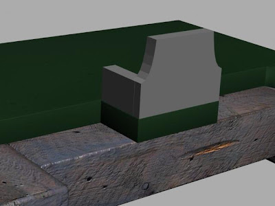
As the rest of the group completed their modeling aspect of the project, I decided to make a start on the animation. The first thing that I noticed was that there was a section that needed to be removed from the base model. This section laid just where the front square was situated. With this section there, I would have been unable to animate the front arms because this would have got in the way. To remove this segment, I simply isolated the object, then used the cut tool to create lines around the area that I wanted to remove. I then selected 'polygon' in the editable poly mode and removed each polygon accordingly. I then needed to cap the ends as they were left vacant. The images below show where the section has been cut out (Creating a 'T' shape rather than two separate objects).

(Base before the section had been remove)
.jpg)
(Base after the section had been removed)
To make the model look even more realistic, I decided to start adding a few textures to see how the model looked once they were applied. I have added a red texture created in Photoshop onto the arms, and will be adding further textures at a later date. Changing the parameters, I was able to create an effect on the texture that made it look more metalic. I changed the texture to anistropic in the basic perameters and altered the specular highlight to create a reflection from any light that is cast onto it. The settings are shown below:

The image below shows the arms with textures applied:

The same technique was used for the metal caps and the ring around the front arm:


Friday, 13 November 2009
Reflection from meeting (12/11/09)
The meeting today was relatively productive.

Although the group had not completely finished the modeling aspects of the project, we were able to put together everything that we had done so far, to see how it looked. Below is the image of the progress so far, without any textures or animation:
I was initially very pleased with how the model was coming along. The size scale that everyone used matched correctly, and there were no aspects of the model that didn't fit together. As you can see from above, there is still quite a lot of work to be done on the modeling before we can really attack the textures and animation. Now that I had completed my modeling aspect, the group decided that it would be a good idea for me to make the initial start on the animation, alongside Richard. The group then agreed that Stuart could work on the environment where the machine will be situated within. Tom would then work on the story board, and develop a plan of action for the short movie that we will eventually make.
Our aim for next week is to bring all of the final modeling aspects together, and create one final model. We will then all work from the same file, where Richard and myself will create the animation and Tom and Stuart will work on textures, lighting and the environment.
Tuesday, 10 November 2009
Final modeling stage
 (Object located behind the front arms)
Behind the two front animated objects, there is one final object that the team agreed I would model. This object was created by using the line tool and drawing a simple rectangle. I then used the cut tool to draw in more lines down the middle so that more vertices appeared at either end of the rectangle. Using the uniform scale tool, I then selected these vertices at the end and pulled them out slightly, focusing on pulling the middle vertices out further than the ones towards the edge. This in turn created an arc shape on the ends (See above). I then extruded the object to the correct depth, and selecting the edge in editable poly mode, I capped the back so that it became solid.

(Objects created to be applied to the previous object)
As shown above, these three objects need to be included so that the previous object that I created can be applied to it. I created a chamfered cylinder that matched the same size as the one at the very front of the model. I then created another chamfered cylinder which was less than half a centimeter in depth, but slightly wider than the first one. Finally, I added a chamfered box which created the small stump that protruded from the middle cylinder.
 (Objects all joined together)
The last task for this part of the project was to rotate the modified cylinder and place it into position onto the other three objects. This has now finalised the small arm that is located behind the two front animated arms. As you can see from above, this is now a very close representation of my original source photo.

(Additional detail to the end arcs)
Just when I thought that the model was complete, I noticed that there was a bolt and two triangles at either end of the model, attached to the end arcs. So, I cloned a bolt, and placed it in the correct position above. I then used the lines spline tool to draw a triangle, and extruded it in the usual way with a slight chamfer modification. I then cloned this object and placed it on the other side of the bolt. Cloning these three objects, I then moved a copy of them down to the other end of the model.
The modeling aspect of this assignment, for me, is now virtually complete, although I am sure that there will inevitably be some additional work required. I will be adding the adequate textures to the model, as at present, the modeled aspects are only coloured rather than textured. This will be done alongside the other members of the group. We will then collate all of our created models on Thursday 12th November, where we will hopefully have a completed model. Once textures have been applied, we will then animate the model using the videos that we took. Lighting and video caption will then be adhered to in order to have a final movie that we will then show to the museum.
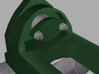
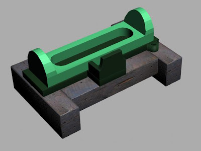
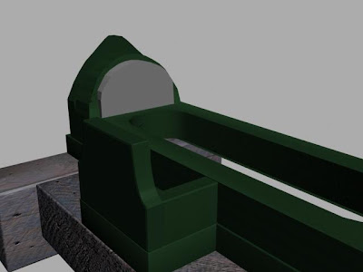
Below are a selection of images of the finished model (without textures) from various angles:
 (Final image of model)
(Final image of model - Close-up)

(End view of model)

(Rear view of model)

(Diagonal rear view of model)
Friday, 6 November 2009
Arm number 2
After creating the first arm, I was then hit by a stroke of good luck. I noticed that the second arm behind was very similar to the first arm that I created. So, I was able to clone the first arm and rotate it 180 degrees. This arm is quite a bit shorter than the first one, so I had to scale it down slightly. Although I thought that this would be easy to do at first, I soon found that it was not so. As the arm was at a slight angle, I had to re-position the arm so that it lay perfectly horizontal. I could then correctly scale the arm down without it altering shape. I then had to rotate the arm again to the necessary angle. Another hard part to this section was trying to select every object that is Incorporated within the arm. As the arm is made up of many objects, it was quite difficult to select every object. However, with lots of incorrect selections and frustration, I finally selected all objects and was able to work on it as required.


(2nd arm in place)
I am now coming very close to the completion of my modelling task, with only a few things left to do. Having started work on this model very early and putting in a lot of hours initially, I am pleased with the way that it looks and am also please with how quickly I was able to create what I have so far.
(Close-up of additional detail)
When I duplicated the arm, I added another metal cap object onto it, as the original source photo shows.
Using the clone tool, I made another copy of the end base plate and nuts/bolts that were attached to it. The scale tool then enabled me to make this a lot more smaller, and I rotated the object 180 degrees. As you can see above, I then placed this at the end of the 2nd arm, and attached the two together. This is now ready for when Tom has finished modeling his section, so that we can connect the two objects together (Tom's model and mine).
Reflection from meeting (29/10/09)
Reflecting on the team meeting on 29th October, I feel that the group has made a lot of progress. We have clear ideas on exactly what it is that we wish to achieve and also clear targets that we have set ourselves. Issues that may arise in the near future have been highlighted so that the whole team are aware. This includes issues relating to all members using the same scale (cm) so that when all of the four main sections come together, they are all able to be joined to one another.
I feel that the team are all very strong at creating models in 3D Studio Max and I am feeling positive about our approach to animation when that comes along.
Although we have been only working on the modeling aspect for one week, the team are getting very close to starting the animation aspect. Because of this, we decided to set the next deadline as Thursday 12th November, where we will start to create some animation. As I have finished the main structure of the base, the rest of the members took a copy of this. We did this so that the model would all come together and connect at the correct places once everyone had finished the separate sections.
To share the workload, we decided that every week a new member of the team would write the minutes to each meeting. I wrote the minutes to week one, Stuart is doing the second week and Richard and Tom will be doing weeks three and four.
Next week we will be merging all of our model to create the final product. From there, we will then be applying textures and animating the model. Group discussion then led onto incorporating various sounds and even having a voice over, explaining about the model and what it was used for etc.
Wednesday, 4 November 2009
Creating the animated arm (Part 2)
 (Cylinder used to create the holes for the bolt)
As there is a bolt that goes through the end cylinders, I decided to create a tube that ran through both of them. I then cloned this object, making an exact copy. Using the Boolean tool, I selected one of the end cylinders, and chose the tube as the operand B. I repeated this for the other end cylinder. This then left me with a hole going through both end cylinders, ready for a bolt to be placed there.

As I knew that there would be an object placed between the two end cylinders, I decided that I did not need a bolt going right through both of them. As such, I copied one of the bolts that I had created previously and scaled it down so that it could be placed within the second cylinder. I made sure that it only protruded out the back of the model. As can be seen from the image above, this now will look like the bolt runs right the way through both cylinders, even though it does not.

(Extension of the arm added)
The extension of the arm was created by placing a sphere in the area where the bolt would have gone through. A simple cylinder then made the arm extension. I then cloned another nut and bolt, and placed this at the end ready to be connected to the end segment that Stuart is currently creating.

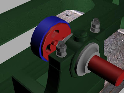
(Additional detail added to the top of the wheel)
Using the metal cap that Richard created, I placed this on top of a chamfered box slightly to the side of the wheel. We believe that these metal caps were used to pour oil into, in order to keep the machine well lubricated. I then created another two boxes similar to the first one, where I then placed them on top of the wheel. Using the clone tool, I then positioned a nut to the left side of the boxes and a bolt head to the right side of the boxes. This then gave the impression that the two boxes were held together by this bolt. The difficult part of this section was sizing the metal cap that Richard created. When I merged this with my document, it was far larger than what I required. As such, I then re-scaled the object so that it was a suitable size.

(Friction plate)
To create the friction plate, I simply drew a chamfer box and set the level so that it was only barely chamfered. As this made the plate look slightly rigid around the edge, I decided to add a Turbo smooth to this object, so that when it rendered it had a smooth surrounding.
Creating the animated arm
 (Arm added to the circular disk)
To create the arm shown above, I first created a standard chamfered box, making sure that the fillet level was correct to match the rest of the model. Converting this to an editable poly, I then selected all of the end vertices on the right hand side and used the scale tool to pull them slightly closer to each other. This in turn made the end of the arm slightly narrower. I then scaled the rest of the arm so that it matched my original source photograph.

(Box and NGon created to make the end of the arm)
First, I created an NGon within the splines object type. This created a 2D object with six sides. I then converted this to an editable poly and selecting the polygon mode, I extruded it. Next, I created a chamfered box at the end of the arm, and sized it accordingly. So that I could get the cut-away shape inside this box, I used the NGon that I had created, and placed this within the box, as shown above.
 (Boolean tool applied and cylinders added)
Selecting the box at the end, I used the Boolean tool and chose the NGon as the operand B. This gave me the nice cutaway that you can see at the end of the arm. I then added a chamfered cylinder and sized this accordingly. This was then cloned across to the other side, and placed in the adjacent position to the other cylinder. All that was required then was another chamfered cylinder similar to the one I had just created, only this one needed to be slightly smaller. I will add the relevant textures to the model towards the end of the project.
Tuesday, 3 November 2009
Initial stage of the first animated object
 (Bolts created and placed within the nuts)
 In order to create the bolts, I first used the 'hose' tool within the extended primitives section and drew a rough hose shape. Converting this to an editable poly, I was then able to alter the end of the bolt so that the vertices were a little closer together as when I initially drew the hose, the end was too wide and flat. Once I was happy with how the bolt looked, I scaled it down and placed it within the nuts. Using the clone tool then enabled me to replicate this to be placed within the other two nuts.
(Nuts and bolts cloned onto the end base plate)
Now that the nuts and bolts are created, I decided to clone them for the end base plate. So, I selected the bolt, washer and one of the nuts and right clicked. Selecting the clone tool and choosing 'copy', I then created a copy of the objects. I then rotated them and dragged them onto the end base plate. As the nut, bolt and washer were a little small, I selected them all and scaled them to make them slightly larger. This then gave me an exact representation of my original source photo.

(Replicating the spindal and protector)
Taking a closer look at a photograph that we took at the museum, I noticed that the spindal ran through to the other side of the front panel, and that there was another protector on the other side. As such, I used the select and uniform scale tool to make the spindal longer and appear approximately three centimeters further out the other side. I then used the clone tool to create a replica of the protector, that will eventually have a gold texture applied.

(Capsule created and modified)
I decided to create the object as shown above. It will become clear in the next stage why I decided to make this. So, first I used the 'capsule' tool to create a standard horizontal capsule. I then converted this to an editable poly and selected the vertices option. Highlighting the two middle vertical rows of vertices, I then dragged them in towards each other using the scale tool, then used the move tool to place them slightly higher. This then left me with this 'jelly bean' shape.

(Cylinder after the boolean tool)
As can be seen from the image above, I first created a chamfer cylinder. Cloning the 'jelly bean' shape that I created in the last stage, I then positioned them in the correct place where they have now removed a chunk out of the cylinder. I then selected the cylinder, and used the Boolean tool, choosing one of the 'jelly bean' shapes as the operand B. I repeated this process, which then left me with two sections missing, which are in the shape of a jelly bean.
(Tube created around the cylinder)
I have now started the creation of the first object that will be animated. This is the moving arm at the front of the pump. Creating a standard tube around the cylinder that I created has enabled me to continue with the rest of the front arm, which I shall do so within the next section.
Yet more work on the front panel
 (Ball and cylinder to create the top of the front panel)
I noticed that at the top of the front panel of the model there is a shape that looks very similar to a standard cylinder with a circular dent in the top. As such, I created the cylinder and placed a sphere in the middle. Selecting the cylinder and choosing the Boolean tool, I was then able to chose the sphere as the operand B object, which then removed the sphere and left a nice dent in the top of the cylinder. I repeated this process, only with a long cylinder in the centre of the main cylinder this time, which provided the hole down the middle.

(The result of the two objects after the Boolean modifier)
As shown above, the effect is yet again very promising. I am very pleased with the replication of this front panel now and feel that it looks similar to the original image that I am working from. The cylinder that has been added at the front is a simple chamfered cylinder with the correct size and fillet level applied.

(NGon created for the nut)
Noticing that there are quite a lot of nuts and bolts within this model, I felt that it was a good time to start creating some. I also knew that once I had created one, I would be able to replicate it many times for most of the other nuts and bolts. So, I started by using the NGon tool within the splines modifier panel. This then provided me with the 6 sided shape as shown above. I then used the extrude tool, which gave me a 3 dimensional object. Converting this to an editable poly and selecting all of the edges, I then altered the chamfer level so that they became very rounded, rather than square. This then created the nuts shown below, and once bolts are placed within these nuts, it will then look far more realistic. Washers (Simple, very thin cylinders) have been placed below the nuts to add to the effect and to also match the original source image. I am now able to clone this object as and when I require more.

Adding detail to the model
 (Front panel detail)
Creating a standard chamfered cylinder and rectangle, I then set the chamfer (fillet) level so that it matched the rest of the front panel. I then scaled the cylinder and rectangle to the correct size and placed them onto the current model where they needed to go. The cylinder needed to protrude slightly as in the source photo, this section stands out more than the rest of the model.

(With Texture)
Adding the dark green texture that I have used for the rest of the model made the cylinder and rectangle look a lot more realistic in resembling my original source image.

(Cylinder and Torus)
As with many models in 3D Studio Max, there are many ways of creating them. For the gold colour section on the front, I decided that the best method here would be to create a cylinder and a torus, then use the Boolean too. So, once both objects were created I selected the cylinder. Using the Boolean tool in the compound objects section, I then selected the 'pick operand B' command, and chose the Torus. This then deleted the Torus and left me with a cylinder with the perimeter cut away.

(Cylinder after the torus has been removed)
As can be seen from above, the outcome is very effective. The Torus has been removed by the Boolean tool, and the cylinder has a nice indentation all around the edge. It took me a couple of attempts to get the Torus in the right position, primarily because the depth was quite hard to judge. Through trial and error, I managed to overcome this issue and was left with an object very similar to that of the one in my source photo.

(End base plate)
Behind the end base plate is a simple cylinder object. Although it is quite difficult to see this shape from the original source photo, I know that it is a cylinder because I remember this from when we visited the museum, and I also used some of our other photo's to confirm that this was in fact the shape behind the end base plate. To create the base plate itself, I used the lines spline tool. Within the front view, I drew a shape that was similar to the shape in the source photo. Using smooth in both the initial type and drag type within the creation method parameter, I was able to get a smooth edge around the object, rather than one that was rigid and too square. Converting it to an editable poly, selecting the polygon, then extruding it to the required length gave me some depth to the object. Finally, I rotated the object and positioned it to where it needed to go. There was some slight alterations that needed to be made to the size of it, but this was really just a finishing touch to get it to the perfect size as shown in my main source photograph.
Monday, 2 November 2009
Arcs at either end
 (Arc created in the left side view)
Similar to the way that I made the first arc in the previous post, I created another one using the line tool again. This arc, however, was slightly larger than the other one I created, mainly protruding at the top. I then converted this to an editable poly, selected 'polygon' within the editable poly options and used the extrude tool. I then scaled it to the correct size to fit in at the end of the model. I then used the clone tool to create an exact replica of this arc and positioned this clone at the opposite end of the model.

(Arcs at either end)
Now that the arcs are created at either end as shown above, the last step was to drag and drop the dark green material onto them that I created in Photoshop. I have encountered the same problem again where the edges are not very smooth around the arc. As mentioned previously, I shall address this issue later by testing some of the smooth options and other modifiers when the group comes together at the end to make final adjustments to textures and mapping.
Main structure of the model
 (Using the Boolean tool to create the front panel)
To create the front of the model, as shown above, I first drew a standard rectangular box. Then, using the line spline tool, I created a shape that would be suitable for cutting out an area of this box to effectively make the corner cut-away. I then converted this to an editable poly, and selected 'polygon' within the editable polygon options. Using the extrude tool then gave the shape some depth (approximately 5 cm). Selecting the rectangular box, I then chose the boolean tool within the compound objects section, then clicked the 'pick operand B' selection, and picked the second object that I made with the line tool. This then deleted the object that I made with the line tool, and removed a section of the rectangle that I required.
(Object mirrored and sides added)
Now that the shape had been created, I then used the mirror tool to create a reflection of this object, making sure that the mirror axis was set to 'X' and the offset was 8.149cm (copy). This is shown below. I then created two standard rectangles either side, making sure that they were the same depth as the first object I created, and the correct length. The last task for me to do was to add the dark green texture that I created in Photoshop, the same as I did for the main base plate.

(Settings used for the mirror tool command)
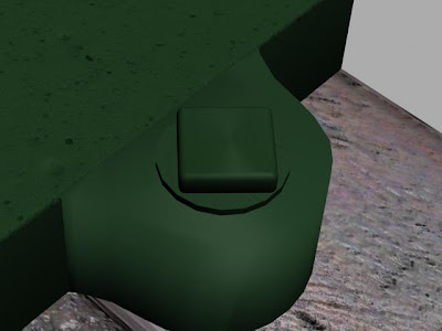
(Additional detail for the nut and bolt)
At this stage, I noticed that there was further detail required for the bolt that holds the machine down onto the wooden blocks. As such, I created a cylinder that was very thin, and placed this below the bolt that I had created, lifting the bolt up very slightly so that it fitted underneath. I then scaled this cylinder down so that it was the correct size according to the source image. I was pleased with this outcome, as it looks far more realistic now witht the washer included.

(Left view of the model)
There were many ways that I could go about creating the main section of the model. I could have created it in many sections, but the way that I thought would be most effective, was to create the main object, then us the boolean tool to remove sections. So, as you can see from above, I used the line tool to draw the side profile of the object. I then closed the splines. Using the extrude tool, I was then able to create a long object. This was then scaled to fit the entire length of the metal base:

(Effect of the extrude tool)
As you can see from the image above, the extrude tool has allowed me to have the arc shape that I created in the left view to stretch across the entire base. At this stage, I realised that there was a slight problem with this. Where I have created the object using the line tool, the arc shape is not very smooth, and this may cause me trouble late on, particularly when texture is added. I shall address this problem later on with Tom, when the group come together towards the final stages to finalise textures and mapping.

(Box created ready to use the Boolean tool)
First, I scaled the arc shaped box inwards slightly, as I noticed that there were other slightly larger arcs at either end.The boolean tool is probably the most used tool within 3D Studio Max. I certainly seem to use it more than any other tool. So, I created a box. This was then converted to an editable poly, where I pulled the bottom vertices of the box in slightly so that the extruded arc would not be completely vertical at the edges, but have a slight slant to them. Selecting the arc object, I once again chose the boolean tool, and picked the box I had just created as the 'operand B'.
(After the Boolean tool had been applied)
The boolean tool left me with the image above. However, I have also used the boolean tool again on a chamfered box so that the arc shaped object went right through to the base unit.
 (Removing the bottom panel)
Looking again at my original source image, I noticed that the middle of the machine and base was completely empty, and you can see right through to the floor when looking from a birds-eye view. So, I created another chamfered box onto the metallic base, and used the boolean tool to remove a segment from the base. This then left me with the image below, where there is a large gap with no fill:

(Image showing a complete gap in the middle of the object)
As with every section, I applied the required material. In this case, it was the dark green material/texture that I originally created in Photoshop.
(Creating the indentation at the ends)
At either end, there are indentations that go into the arcs. These are important, because they then make the arcs perfectly vertical within the indentation rather than being slanted as I created them. I will need the ends to be vertical later on because there will be objects that will need to lay flush to a vertical object.
So, I created a smaller arc to the existing one, the same way as I did previously. Using the clone tool, I was able to replicate this arc at the other end of the model. I then selected the main model object, and used the Boolean tool to remove the arc object and a segment within the main model. Repeating this at the opposite end of the model gave me the required indentation.
Subscribe to:
Posts (Atom)
