 (Using the Boolean tool to create the front panel)
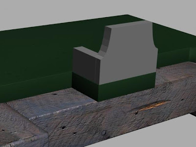
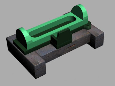
(Object mirrored and sides added)
Now that the shape had been created, I then used the mirror tool to create a reflection of this object, making sure that the mirror axis was set to 'X' and the offset was 8.149cm (copy). This is shown below. I then created two standard rectangles either side, making sure that they were the same depth as the first object I created, and the correct length. The last task for me to do was to add the dark green texture that I created in Photoshop, the same as I did for the main base plate.

(Settings used for the mirror tool command)
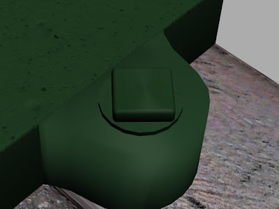
(Additional detail for the nut and bolt)
At this stage, I noticed that there was further detail required for the bolt that holds the machine down onto the wooden blocks. As such, I created a cylinder that was very thin, and placed this below the bolt that I had created, lifting the bolt up very slightly so that it fitted underneath. I then scaled this cylinder down so that it was the correct size according to the source image. I was pleased with this outcome, as it looks far more realistic now witht the washer included.

(Left view of the model)
There were many ways that I could go about creating the main section of the model. I could have created it in many sections, but the way that I thought would be most effective, was to create the main object, then us the boolean tool to remove sections. So, as you can see from above, I used the line tool to draw the side profile of the object. I then closed the splines. Using the extrude tool, I was then able to create a long object. This was then scaled to fit the entire length of the metal base:

(Effect of the extrude tool)
As you can see from the image above, the extrude tool has allowed me to have the arc shape that I created in the left view to stretch across the entire base. At this stage, I realised that there was a slight problem with this. Where I have created the object using the line tool, the arc shape is not very smooth, and this may cause me trouble late on, particularly when texture is added. I shall address this problem later on with Tom, when the group come together towards the final stages to finalise textures and mapping.

(Box created ready to use the Boolean tool)
First, I scaled the arc shaped box inwards slightly, as I noticed that there were other slightly larger arcs at either end.The boolean tool is probably the most used tool within 3D Studio Max. I certainly seem to use it more than any other tool. So, I created a box. This was then converted to an editable poly, where I pulled the bottom vertices of the box in slightly so that the extruded arc would not be completely vertical at the edges, but have a slight slant to them. Selecting the arc object, I once again chose the boolean tool, and picked the box I had just created as the 'operand B'.
(After the Boolean tool had been applied)
The boolean tool left me with the image above. However, I have also used the boolean tool again on a chamfered box so that the arc shaped object went right through to the base unit.
 (Removing the bottom panel)
Looking again at my original source image, I noticed that the middle of the machine and base was completely empty, and you can see right through to the floor when looking from a birds-eye view. So, I created another chamfered box onto the metallic base, and used the boolean tool to remove a segment from the base. This then left me with the image below, where there is a large gap with no fill:

(Image showing a complete gap in the middle of the object)
As with every section, I applied the required material. In this case, it was the dark green material/texture that I originally created in Photoshop.
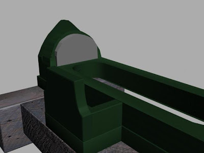
(Creating the indentation at the ends)
At either end, there are indentations that go into the arcs. These are important, because they then make the arcs perfectly vertical within the indentation rather than being slanted as I created them. I will need the ends to be vertical later on because there will be objects that will need to lay flush to a vertical object.
So, I created a smaller arc to the existing one, the same way as I did previously. Using the clone tool, I was able to replicate this arc at the other end of the model. I then selected the main model object, and used the Boolean tool to remove the arc object and a segment within the main model. Repeating this at the opposite end of the model gave me the required indentation.

No comments:
Post a Comment