Richard began creation of the fly wheel and Tom began to create some more detailed aspects, such as bolts that will be replicated across the model.
As can be seen from my previous posts, I have already sucessfully created the base of the model, which I shall be building up over the next few days. Then I shall progress on to creating some of the main arms that are animated in the middle of the model. As there are four main sections to our model that we chose, the tasks are easily spread across each member of the team.
The presentation:
Prior to the presentation, I created a few powerpoint slides containing information about our project. Things like roles and responsibilities, foreseeable problematic areas etc. I feel that this presentation went very well and it gave every member within the group a chance to explain to the rest of the class what our project is all about and how we will go about completing this project.
Our presentation was widely accepted by Jo Bowman and the class, and as a team we have a direct goal and specific aims that we know we must complete. The team are now ready to get to work on creating the model, and the work that has been created so far is looking very promising.
The slides from the presentation are shown below:


These sites showed us how the machine was created and also provided us with more pictures that we will be able to use for animation purposes. Background information on the machine also provided us with knowledge of where it would have been used, so hopefully we will be able to create a model in 3DS Max of a colliery to add to the affect of the machine working.


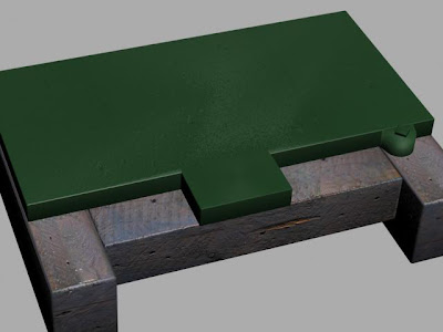

 Then, using the parameters section, I could then scale the boxes to the correct size. The first box that I created measured 60.96cm in length and 10.95cm in width. The height was 14.99cm. I could also set the fillet level to 0.51cm so that the edges became rounded rather than completely square. Placing this object in the correct position as per my reference photograph, I then used the clone tool to create an exact copy and placed the second object where it needed to go. The clone tool setting that I used for this is shown below:
  Now that both side boxes were complete, I then created the middle chamfer box, as shown in the image above. Doing this in the same way, I selected the same depth for this object, and made sure that it was wide enough to fit between the first two boxes without a gap between. I then made sure that the fillet level was the same as per the other two boxes that I created.


